CONTROL VALVES OF EYVAZ
Pneumatic Control Valve NCV Type 24-11
In this lecture , we have a brief description about the control valves . In addition , if you want any technical service you can contact our expert person . Upon request of the price of any of the above mentioned you can fill the form and contact to our sales department.
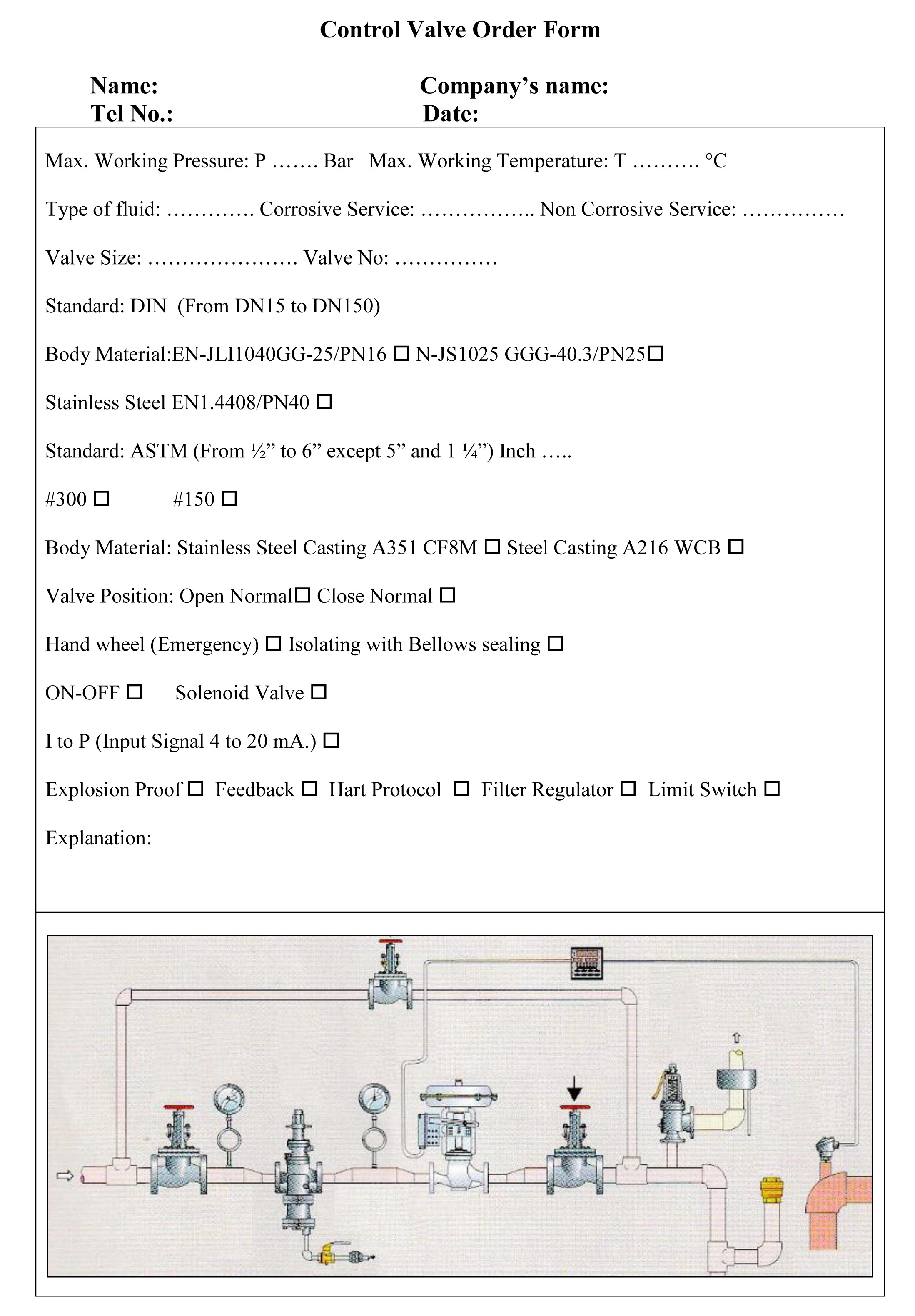
For presenting the control valves price, we should consider some points. We set a form that you can complete it for reaching pneumatic valves price. In addition, you can contact our sales department.
A control valve is a power-operated device capable of modulating at varying degrees between minimal flow and full capacity in response to a signal from the controlling system. Control valves may be broadly classified by their function as on-off type or flow regulating type. There are many types of valves available, each having their advantages and limitations. The basic requirements and selection depend on their ability to perform specific functions.
Gate valve, Globe valve, Ball valve, Butterfly valve, Plug valve, Rotary valve, Check valve, Diaphragm valve, needle valve, safety valve.
The best valve is Globe valves. Globe valves are extensively employed to control flow. The range of flow control, pressure drop, and duty must be considered in the design of the valve to avert premature failure and to assure satisfactory service.
Design of Globe valves:
Body: The horizontal setting of the seat allows the stem and disk to travel perpendicular to the horizontal line. This design has the lowest coefficient of flow and higher-pressure drop.
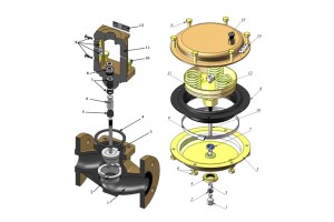
Bonnet: Bonnet is part of the valves that it prevents system pressure from the building against the valve packing, when the valve is fully open. Bonnet is a guider and involve the packing.
Stem Globe valves uses two methods for connecting the disk and the stem. Stem cause to plug movement in body valves.
Plug: A term frequently used to reference the valve closure member in a sliding-stem valve.
Seat: The area of contact between the closure member and its mating surface that stablishes valve shut off.
Actuator: It is the main part. It converts the pressure and power on valve. At the result, it causes to cut or adjust the fluid on the valves.
I to P positioner: It is use for gradually and exactly controlling on the valves. In addition, we can use for feed backing.
Flow curve valve: In the most valve, we do not have stable flow water. Quick opening valve used for systems where instant large flow is needed and in linear valve used for system where the pressure drop across the valve is expected to remain fairly constant. Equal percentage valve used in system where large changes in pressure drop across the valve are expected.

Cavitation and flashing: Choked flow causes flashing and cavitation, The IEC liquid sizing standard calculates a choked pressure drop. If the actual pressure drop across the valve, as defined by the system conditions of P1 and P2 is greater than P then either flashing or cavitation may occur. Structural damage to the valve and adjacent piping may also result. Knowledge of what is actually happening within the valve will permit selection of a valve that can eliminate or reduce the effects of cavitation and flashing.
The physical phenomena label is used to describe flashing and cavitation because these conditions represent actual changes in the phase of the fluid media. The change is from the liquid state to the vapor state and results from the increase in fluid velocity at or just downstream of the greatest flow restriction, normally the valve port. As liquid flow passes through the restriction, there is a necking down, or contraction, of the flow stream. The minimum cross-sectional area of the flow stream occurs just downstream of the actual physical restriction at a point called the vena contract To maintain a steady flow of liquid through the valve, the velocity must be greatest at the vena contract, where cross-sectional area is the least. The increase in velocity (or kinetic energy) is accompanied by a substantial decrease in pressure (or potential energy) at the vena contract. Further, downstream, as the fluid stream expands into a larger area, velocity decreases and pressure increases. However, downstream pressure never recovers completely to equal the pressure that existed upstream of the valve. The pressure differential (∆P) that exists across the valve is a measure of the amount of energy that was dissipated in the valve. Figure 5.7 provides a pressure profile explaining the differing performance of a streamlined high-recovery valve, such as a ball valve, and a valve with lower recovery capabilities due to greater internal turbulence and dissipation of energy. Regardless of the recovery characteristics of the valve, the pressure differential of interest pertaining to flashing and cavitation is the differential between the valve inlet and the vena contract. If pressure at the vena contract should drop below the vapor pressure of the fluid (due to increased fluid velocity at this point) bubbles will form in the flow stream. Formation of bubbles will increase greatly as vena contract pressure drops further below the vapor pressure of the liquid. At this stage, there is no difference between flashing and cavitation, but the potential for structural damage to the valve definitely exists. If pressure at the valve outlet remains below the vapor pressure of the liquid, the bubbles will remain in the downstream system and the process is said to be flashing. Flashing can produce serious erosion damage to the valve trim parts and is characterized by a smooth, polished appearance of the eroded surface, as shown in Figure 5.8. Flashing is normally greatest at the point of highest velocity, which is usually at or near the seat line of the valve plug and seat ring.

In continue, you can fill the form and put your order until they will prepare in a short time. In the bellow, you can see the form of Azarsam Instrument co. Eyvaz brand name:


